Vorrätig Top‑Produkt
PSR-PC40-2NO-1DO-24DC-SC
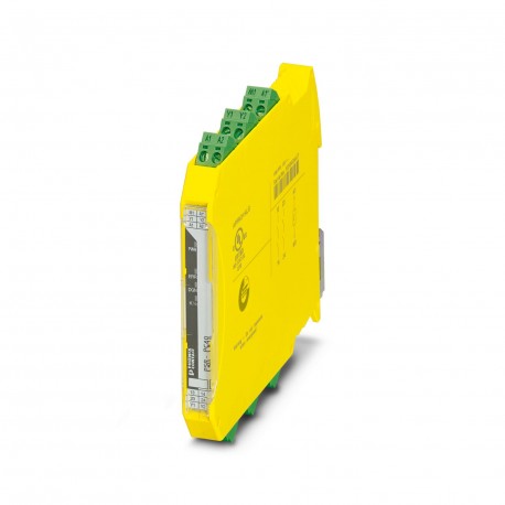
PSR-PC40-2NO-1DO-24DC-SC 2700588 PHOENIX CONTACT Coupling relay
$0.00USD
3654 auf Lager
Wichtige Spezifikationen
:High demand
Tiefe:114.5 mm
Schock:15g
Breite:12.5 mm
Lieferanteninformation
Produkte: 0
Versand in der Regel innerhalb von 2-3 Werktagen
Qualität garantiert
Schneller Versand
Technischer Support
Technische Spezifikationen
| Parameter | Wert |
|---|---|
| High demand | |
| Tiefe | 114.5 mm |
| Schock | 15g |
| Breite | 12.5 mm |
| Höhe | 112.2 mm |
| Aktuell | max. 100 mA |
| Stromspannung | approx. 22 V DC (Us- 2 V) |
| steckbar | yes |
| CCCex-Notiz | Use in potentially explosive areas is not permitted in China. |
| Relais-Typ | Electromechanical relay with force-guided contacts in accordance with IEC/EN 61810-3 |
| Anwendung | Safe switch off |
| Zertifikat | UL 22 ATEX 2912X |
| Bezeichnung | A1/A2 |
| Filterzeit | max. 2 ms (at A1-A2; test pulse width) |
| Ausgangssicherung | 6 A gL/gG |
| Produktart | Coupling relay |
| Schraubengewinde | M3 |
| Montagehinweis | See derating curve |
| Montageart | DIN rail mounting |
| Erholungszeit | 500 ms |
| Stoppkategorie | 0 |
| Identifikation | II 3G Ex ec nC IIC T4 Gc |
| Einschaltstrom | typ. 400 mA (Δt s) |
| Produktfamilie | PSRmini |
| Statusanzeige | 2 x LED (green) |
| Farbe (Gehäuse) | yellow (RAL 1018) |
| Artikelüberarbeitung | 07 |
| Kontaktmaterial | AgSnO2 |
| Fehleranzeige | 1 x LED (red) |
| Gehäusematerial | Polyamide |
| Maximale Höhe | ≤ 2000 m (Above sea level) |
| Anzahl der Eingänge | 2 (Non-safety-related start inputs: Y1/Y2) |
| Abstreiflänge | 7 mm |
| Verbindungsmethode | Screw connection |
| Montageposition | vertical, horizontal, with front of module upward |
| Anzahl der Ausgänge | 2 (safety-related N/O contacts: 13/14, 23/24) |
| Quadratischer Gesamtstrom | 60 A2(observe derating) |
| Schaltspannung | min. 12 V AC/DC |
| Anzugsmoment | 0.5 Nm ... 0.6 Nm |
| Ausgabebeschreibung | 2 NO contacts each in series, without delay, floating |
| Schutzschaltung | Serial protection against polarity reversal; 33 V suppressor diode |
| Schaltkapazität | min. 60 mW |
| Aktueller Verbrauch | < 5 mA |
| Hinweis zur Anwendung | Only for industrial use |
| Schaltfrequenz | max. 0.5 Hz |
| Schutzgrad | IP20 |
| Typische Veröffentlichungszeit | < 35 ms (when controlled via A1) |
| Normen/Vorschriften | EN 60664-1, EN 60079-7, EN 60079-15 |
| Vibration (Betrieb) | 10 Hz ... 150 Hz, 2g |
| Kontaktschaltart | 2 enabling current paths |
| Maximaler Einschaltstrom | 500 mA (Δt = 1 ms at Us) |
| Nominaler Betriebsmodus | 100% operating factor |
| Mechanische Lebensdauer | 10x 106cycles |
| Stromverbrauch in den USA | typ. 1.8 W |
| Bemessungsisolationsspannung | 250 V AC |
| Kurzschlussschutz | no |
| Anzeige der Betriebsspannung | 1 x yellow LED |
| Typische Startzeit bei uns | < 200 ms (when controlled via A1, automatic start) |
| Leiterquerschnitt AWG | 24 ... 12 |
| Begrenzung des Dauerstroms | 6 A (High demand) |
| Sicherheitsintegritätsniveau (SIL) | 3 |
| Leiterquerschnitt starr | 0.2 mm² ... 2.5 mm² |
| Bemessungsstoßspannung/Isolierung | Safe isolation, 6 kV reinforced insulation from control circuit, start circuit, signal output to the enabling current paths, 4 kV/basic insulation between the enabling current paths and between all current paths and housing |
| Umgebungstemperatur (Betrieb) | -40 °C ... 70 °C (observe derating) |
| Bemessungssteuerstrom IS | typ. 75 mA (depending on load M1 +100 mA) |
| Leiterquerschnitt flexibel | 0.2 mm² ... 2.5 mm² |
| Umgebungstemperatur (Lagerung/Transport) | -40 °C ... 85 °C |
| Bemessungsversorgungsspannung des Steuerkreises (US) | 20.4 V DC ... 26.4 V DC |
| Mindestschutzgrad des Anlagenstandorts | IP54 |
| Spannung am Eingang/Start und Rückkopplungsschaltung | 24 V DC -15 %; +10 % |
| Maximal zulässige Luftfeuchtigkeit (Lagerung/Transport) | 75 % (on average, 85% infrequently, non-condensing) |
| Maximal zulässiger Gesamtwiderstand des Leiters | 150 Ω |
| Maximal zulässige relative Luftfeuchtigkeit (Betrieb) | 75 % (on average, 85% infrequently, non-condensing) |
| Maximale Verlustleistung im Nennbetrieb | 5.5 W (IL² = 60 A²) |
| Schaltleistung gemäß IEC 60947-5-1 | 4 A (24 V (DC13)) |
Produktbeschreibung
Coupling relay for high and low demand applications SIL 3, couples digital output signals to the periphery, 2 trip circuits, 1 digital warning output, Safe-State-Off applications, test pulse filter, p
Hauptmerkmale
- Qualität in Industrieklasse
- RoHS-konform
- CE-zertifiziert
- 1‑Jahresgarantie
Produktdokumente
Datenblatt
Technische Spezifikationen und Leistungsdaten
Benutzerhandbuch
Installations- und Betriebsanleitung


