Vorrätig Top‑Produkt
IB IL TEMP 2 UTH-PAC
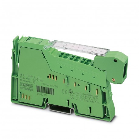
IB IL TEMP 2 UTH-PAC 2861386 PHOENIX CONTACT Inline terminal
$0.00USD
3005 auf Lager
Wichtige Spezifikationen
:Failure of or insufficient communications power ULI/O error message sent to the bus coupler
Typ:modular
Tiefe:71.5 mm
Breite:12.2 mm
Lieferanteninformation
Produkte: 0
Versand in der Regel innerhalb von 2-3 Werktagen
Qualität garantiert
Schneller Versand
Technischer Support
Technische Spezifikationen
| Parameter | Wert |
|---|---|
| Failure of or insufficient communications power ULI/O error message sent to the bus coupler | |
| Typ | modular |
| Tiefe | 71.5 mm |
| Breite | 12.2 mm |
| Höhe | 136.8 mm |
| CCCex-Notiz | Use in potentially explosive areas is not permitted in China. |
| Eingabename | Analog UTH inputs |
| Aktueller Stromverbrauch | max. 60 mA |
| Produktart | I/O component |
| ID-Code (hex) | 7F |
| Montageart | DIN rail mounting |
| ID-Code (Dez.) | 127 |
| Betriebsart | Process data operation with 2 words |
| Produktfamilie | Inline |
| Versorgungsspannung | 7.5 V DC (via voltage jumper) |
| Verbindungsname | Inline connector |
| Registerlänge | 32 bit |
| Artikelüberarbeitung | 11 |
| Anzahl der Eingänge | 2 (Thermocouples or linear voltage) |
| Verschmutzungsgrad | 2 (IEC 60664-1, EN 60664-1) |
| Schutzklasse | III (IEC 61140, EN 61140, VDE 0140-1) |
| Abstreiflänge | 8 mm |
| Verbindungsmethode | Inline data jumper |
| Längencode (dez) | 02 |
| Längencode (hex) | 02 |
| Lieferumfang | including Inline connector and labeling field |
| Eingabeadressbereich | 4 Byte |
| Hinweis zu den Abmessungen | Housing dimensions |
| Schutzschaltung | Surge protection (TC channels); up to ±40 V |
| Getriebegeschwindigkeit | 500 kbps |
| A/D-Wandlungszeit | typ. 120 µs (per channel) |
| Maßzeichnung | |
| Messprinzip | Successive approximation |
| Hinweis zur Anwendung | Only for industrial use |
| Ausgabeadressbereich | 4 Byte |
| Aktualisierung der Prozessdaten | max. 30 ms (For both channels) |
| Schutzgrad | IP20 |
| Diagnosemeldungen | Failure of the internal I/O supply I/O error message sent to the bus coupler |
| Anzahl der Schnittstellen | 2 |
| Überspannungskategorie | II (IEC 60664-1, EN 60664-1) |
| Prozessdatenkanal | 32 bit |
| Versorgungsspannungsbereich | 19.2 V DC ... 30 V DC (including all tolerances, including ripple) |
| Verbindungstechnologie | 2-conductor |
| Erforderliche Parameterdaten | 6 Byte |
| Luftdruck (Betrieb) | 70 kPa ... 106 kPa (up to 3000 m above sea level) |
| Beschreibung der Eingabe | Inputs for thermocouples or linear voltage |
| Leiterquerschnitt AWG | 28 ... 16 |
| Erforderliche Konfigurationsdaten | 4 Byte |
| Leiterquerschnitt starr | 0.08 mm² ... 1.5 mm² |
| Messwertdarstellung | 16 bits (15 bits + sign bit) |
| Leiterquerschnitt, starr | 0.08 mm² ... 1.5 mm² |
| Umgebungstemperatur (Betrieb) | -25 °C ... 55 °C |
| Luftdruck (Lagerung/Transport) | 70 kPa ... 106 kPa (up to 3000 m above sea level) |
| Leiterquerschnitt flexibel | 0.08 mm² ... 1.5 mm² |
| Zulässige Luftfeuchtigkeit (Betrieb) | 10 % ... 95 % (non-condensing) |
| Leiterquerschnitt, flexibel | 0.08 mm² ... 1.5 mm² |
| Verwendbare Sensortypen (TC) | U, T, L, J, E, K, N, S, R, B, C, W, HK |
| Umgebungstemperatur (Lagerung/Transport) | -25 °C ... 85 °C |
| Hinweis zur Verbindungstechnologie | Shielded compensating line for TC with encapsulated sensors |
| Zulässige Luftfeuchtigkeit (Lagerung/Transport) | 10 % ... 95 % (non-condensing) |
| Maximale Verlustleistung im Nennbetrieb | 0.9 W |
| Prüfspannung: 7,5 V Versorgungsspannung (Buslogik)/Funktionsmasse | 500 V AC, 50 Hz, 1 min. |
| Testspannung: 24 V analoge Versorgungsspannung (analoge Ein-/Ausgänge)/Funktionsmasse | 500 V AC, 50 Hz, 1 min. |
| Testspannung: 7,5 V Versorgungsspannung (Buslogik)/24 V analoge Versorgungsspannung (analoge Ein-/Ausgänge) | 500 V AC, 50 Hz, 1 min. |
Produktbeschreibung
Inline, Temperature recording module, Analogue UTH inputs: 2 (Thermocouples or linear voltage), connection technology: 2 conductors, transmission rate on local bus: 500 kBit/s, protection rating: IP20
Hauptmerkmale
- Qualität in Industrieklasse
- RoHS-konform
- CE-zertifiziert
- 1‑Jahresgarantie
Produktdokumente
Datenblatt
Technische Spezifikationen und Leistungsdaten
Benutzerhandbuch
Installations- und Betriebsanleitung


