Vorrätig Top‑Produkt
AXL F AO4 XC 1H
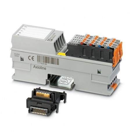
AXL F AO4 XC 1H 2702153 PHOENIX CONTACT I/O module
$0.00USD
3182 auf Lager
Wichtige Spezifikationen
:Transient protection; Suppressor diode
Typ:block modular
Tiefe:54 mm
Breite:35 mm
Lieferanteninformation
Produkte: 0
Versand in der Regel innerhalb von 2-3 Werktagen
Qualität garantiert
Schneller Versand
Technischer Support
Technische Spezifikationen
| Parameter | Wert |
|---|---|
| Transient protection; Suppressor diode | |
| Typ | block modular |
| Tiefe | 54 mm |
| Breite | 35 mm |
| Höhe | 126.1 mm |
| Zertifikat | UL 20 ATEX 2441X |
| Ausgabename | Analog outputs |
| Aktueller Stromverbrauch | max. 150 mA |
| Datenformate | IB IL, S7-compatible |
| Produktart | I/O component |
| Montageart | DIN rail mounting |
| Identifikation | II 3 G Ex ec IIC T4 Gc |
| Produktfamilie | Axioline F |
| Versorgungsspannung | 5 V DC (via bus base module) |
| Verbindungsname | Axioline F connector |
| Artikelüberarbeitung | 07 |
| Verschmutzungsgrad | 2 (IEC 60664-1, EN 60664-1) |
| Schutzklasse | III (IEC 61140, EN 61140, VDE 0140-1) |
| Abstreiflänge | 8 mm |
| Verbindungsmethode | Bus base module |
| Montageposition | any (no temperature derating) |
| Anzahl der Ausgänge | 4 |
| Lieferumfang | including bus base module and Axioline F connectors |
| Eingabeadressbereich | 8 Byte |
| Hinweis zu den Abmessungen | The depth applies when a TH 35-7.5 DIN rail is used (in accordance with EN 60715). |
| Schutzschaltung | Short-circuit and overload protection; electronic |
| Besondere Eigenschaften | Extreme conditions version |
| Getriebegeschwindigkeit | 100 Mbps |
| Maßzeichnung | |
| Hinweis zur Anwendung | Only for industrial use |
| Ausgabeadressbereich | 8 Byte |
| Aktualisierung der Prozessdaten | 140 µs |
| Schutzgrad | IP20 |
| Anzahl der Schnittstellen | 2 |
| Überspannungskategorie | II (IEC 60664-1, EN 60664-1) |
| Versorgungsspannungsbereich | 19.2 V DC ... 30 V DC (including all tolerances, including ripple) |
| Verbindungstechnologie | 2-conductor |
| Stromausgangssignal | 0 mA ... 20 mA |
| Spannungsausgangssignal | 0 V ... 5 V |
| Verweise auf Normen | EN IEC 60079-0, EN IEC 60079-7 |
| Erforderliche Parameterdaten | 14 Byte |
| Luftdruck (Betrieb) | 70 kPa ... 106 kPa (up to 3000 m above sea level) |
| D/A-Wandler-Auflösung | 16 bit |
| Leiterquerschnitt AWG | 24 ... 16 |
| Erforderliche Konfigurationsdaten | 7 Byte |
| Leiterquerschnitt starr | 0.2 mm² ... 1.5 mm² |
| Hinweis zur Verbindungsmethode | Please observe the information provided on conductor cross sections in the “Axioline F: system and installation” user manual. |
| Leiterquerschnitt, starr | 0.2 mm² ... 1.5 mm² |
| Umgebungstemperatur (Betrieb) | -25 °C ... 60 °C (Standard, applications with UL approval, use in zone 2 potentially explosive area) |
| Last-/Ausgangslaststromausgang | ≤ 500 Ω |
| Last-/Ausgangsspannung | ≥ 1 kΩ |
| Darstellung der Ausgabewerte | 16 bits (15 bits + sign) |
| Luftdruck (Lagerung/Transport) | 70 kPa ... 106 kPa (up to 3000 m above sea level) |
| Leiterquerschnitt flexibel | 0.2 mm² ... 1.5 mm² |
| Zulässige Luftfeuchtigkeit (Betrieb) | 5 % ... 95 % (non-condensing) |
| Leiterquerschnitt, flexibel | 0.2 mm² ... 1.5 mm² |
| Umgebungstemperatur (Lagerung/Transport) | -40 °C ... 85 °C |
| Hinweis zur Verbindungstechnologie | shielded, twisted pair |
| Zulässige Luftfeuchtigkeit (Lagerung/Transport) | 5 % ... 95 % (non-condensing) |
| Testspannung: 24 V Versorgungsspannung (E/A)/Analogausgänge | 500 V AC, 50 Hz, 1 min. |
| Prüfspannung: Analogausgänge/Funktionsmasse | 500 V AC, 50 Hz, 1 min. |
| Maximale Verlustleistung im Nennbetrieb | 3.4 W |
| Prüfspannung: 24 V Versorgungsspannung (E/A) / Funktionsmasse | 500 V AC, 50 Hz, 1 min. |
| Prüfspannung: 5 V Versorgungsspannung des lokalen Busses (UBus)/Analogausgänge | 500 V AC, 50 Hz, 1 min. |
| Prüfspannung: 5 V Versorgungsspannung des lokalen Busses (UBus) / Funktionsmasse | 500 V AC, 50 Hz, 1 min. |
| Testspannung: 5 V Versorgungsspannung des lokalen Busses (UBus) / 24 V Versorgungsspannung (I/Os) | 500 V AC, 50 Hz, 1 min. |
Produktbeschreibung
AxiolineF, Analog Output Module, Analog Outputs: 4, 0 V ... 5 V, -5 V ... 5 V, 0 V ... 10 V, -10 V ... 10 V, 0 mA... 20 mA, 4 mA... 20 mA, connection technology: 2 conductors, transmission rate on loc
Hauptmerkmale
- Qualität in Industrieklasse
- RoHS-konform
- CE-zertifiziert
- 1‑Jahresgarantie
Produktdokumente
Datenblatt
Technische Spezifikationen und Leistungsdaten
Benutzerhandbuch
Installations- und Betriebsanleitung


